Wiring the Arduino and Raspberry Pi
Two separate connections need to be established between the Arduino and the Raspberry Pi. A serial data connection over either USB or the RPi GPIO pins and a reset circuit to hard reset the Arduino from the RPi.
Serial Connection
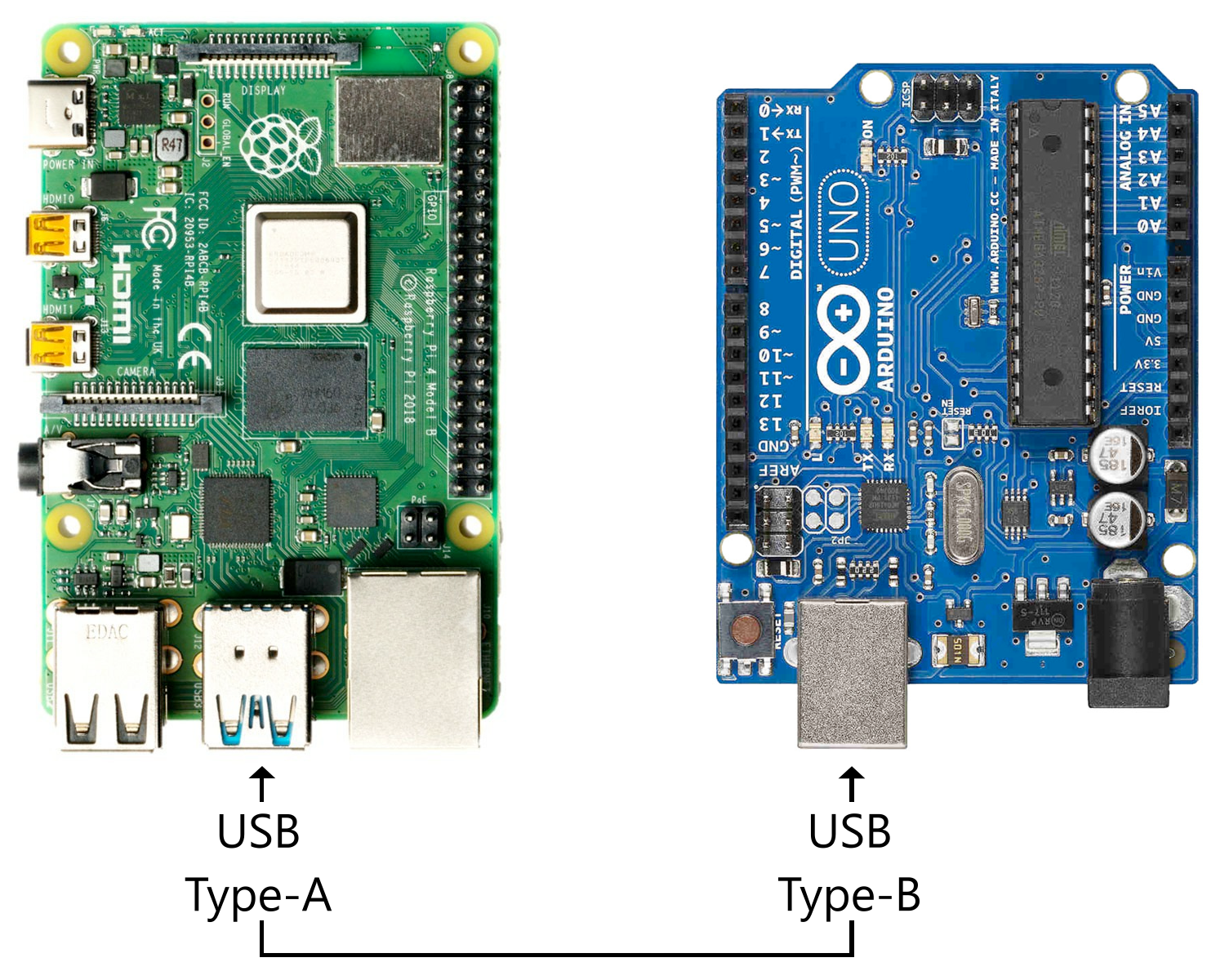
There are two methods of serial connection available between the Arduino and RPi: USB and GPIO pins. USB will be your go-to method, but if the Raspberry Pi's USB ports are already in use or otherwise obstructed, you can utilize the RPi GPIO pins with some extra effort and parts.
Serial Over USB (The Easy Way)
Connect the Arduino and Raspberry Pi via a USB cable.
Serial Over RPi GPIO Pins
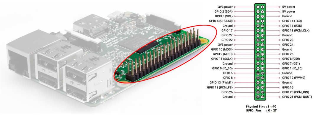
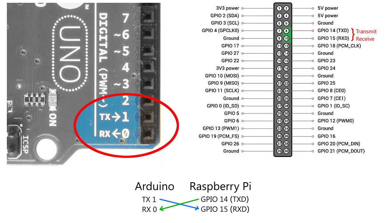
Opposite the display ports of the RPi are two rows of forty pins. Twenty-seven of these pins are general-purpose input/output (GPIO) pins that can be assigned as needed.
⚠️ Warning: It's essential to understand that the Arduino and Raspberry Pi operate at different logic voltages. The Arduino operates at 5V, whereas the RPi operates at 3.3V. Directly coupling them over GPIO pins without some form of voltage regulation will damage the RPi. There are several methods for regulating the voltage between these two, but this guide will only cover using a logic level converter, as it's the safest and least involved method.
You'll need the following or similar components to utilize serial over GPIO:
- Logic Level Converter ($4 Sparkfun link)
- Male-to-Female Dupont Jumper Wires ($7 Amazon link)
- Male-to-Male Jumper Wires ($7 Amazon link)
- A small breadboard or PCB ($7 Amazon link)
What is a Logic Level Converter?
A logic level converter merely steps voltage signals up or down between two independent circuits. In addition to the information provided in this guide, you may also find SparkFun's detailed Hookup Guide helpful.
Enable Serial Over GPIO Pins
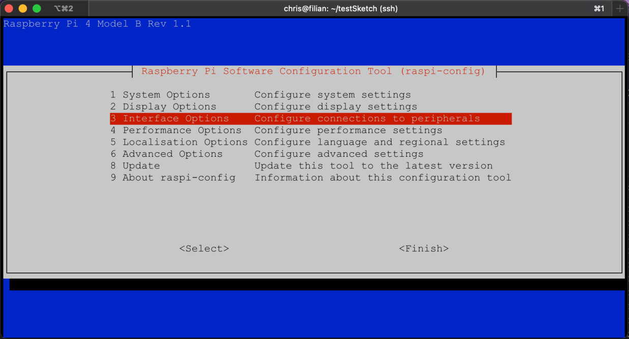
By default, the Raspberry Pi GPIO pins are not enabled and must be activated using the Raspberry Pi Configuration Tool.
sudo raspi-config
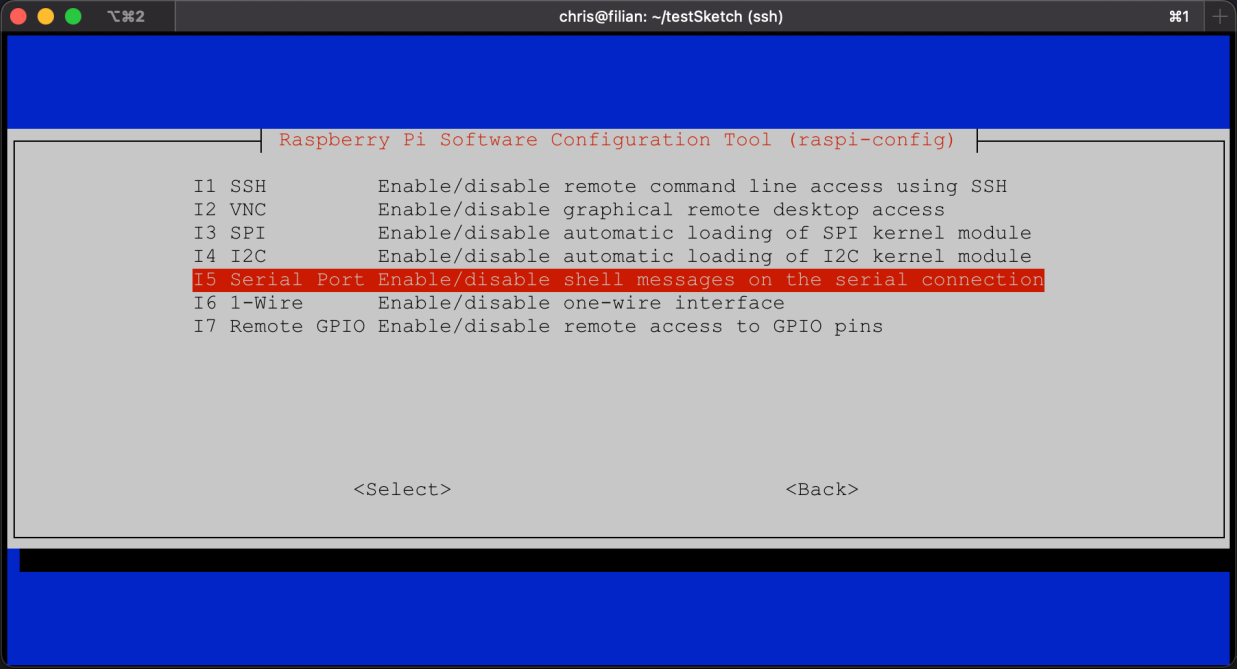
When the tool opens select Interface Options.
Select Serial Port.
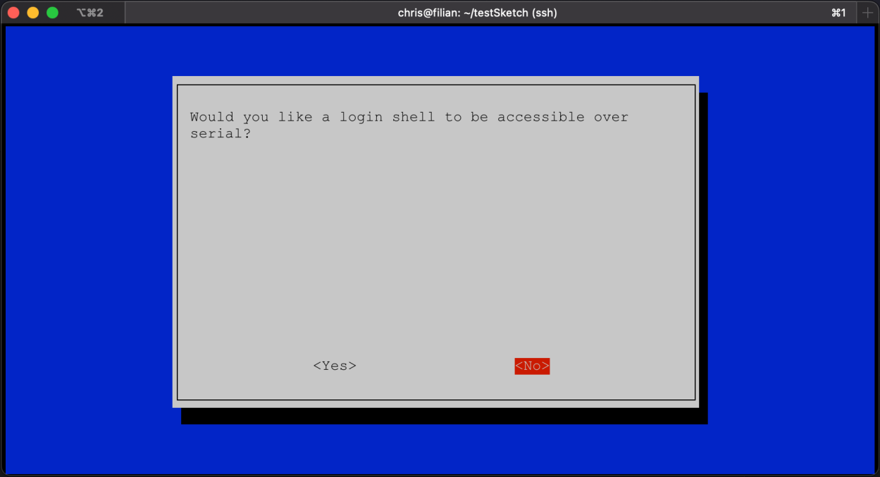
Select No to login over serial.
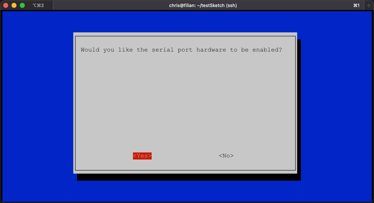
Select Yes to enable serial GPIO hardware.
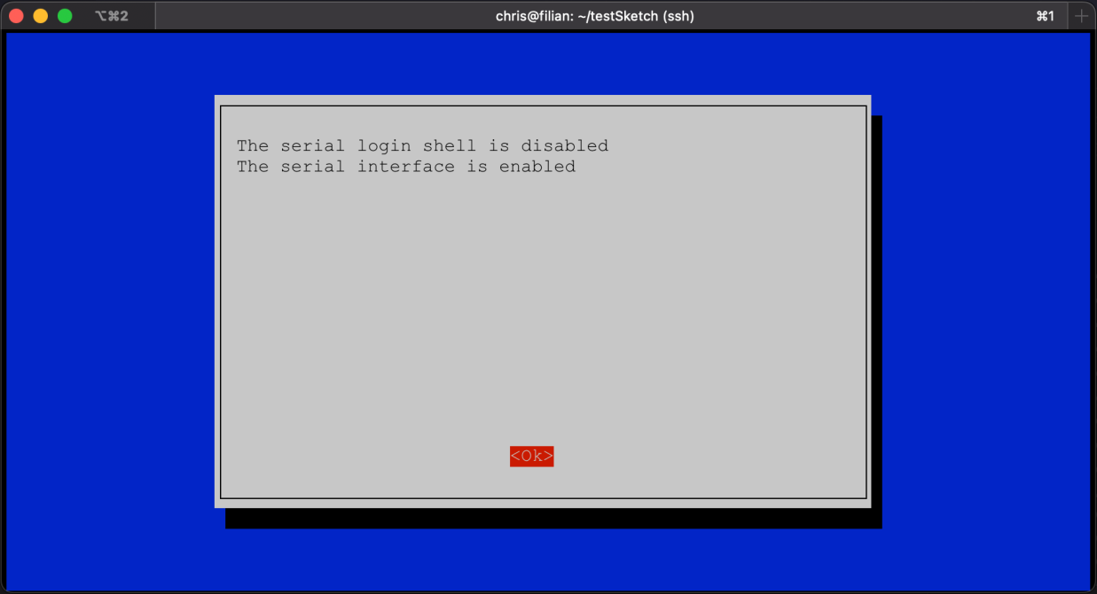
Click OK and then Finish.
Now, restart the Raspberry Pi.
After restarting, you should be able to see the GPIO port ttyS0 using the ls and grep commands.
ls /dev | grep tty
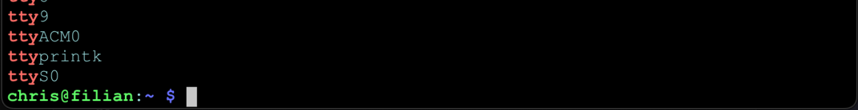
If ttyS0 is listed, the GPIO pins are configured and ready to be wired to the Arduino.
Connecting the Transmit (TX) and Receive (RX) Pins Between the Arduino and RPi
Do not connect pins TX to TX and RX to RX. Instead, cross them between the two devices. Connect the transmit pin of the Arduino to the receive pin of the RPi and the transmit pin of the RPi to the receive pin of the Arduino.
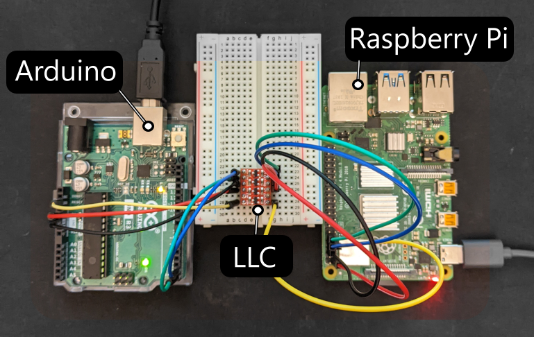
Wiring the Logic Level Converter
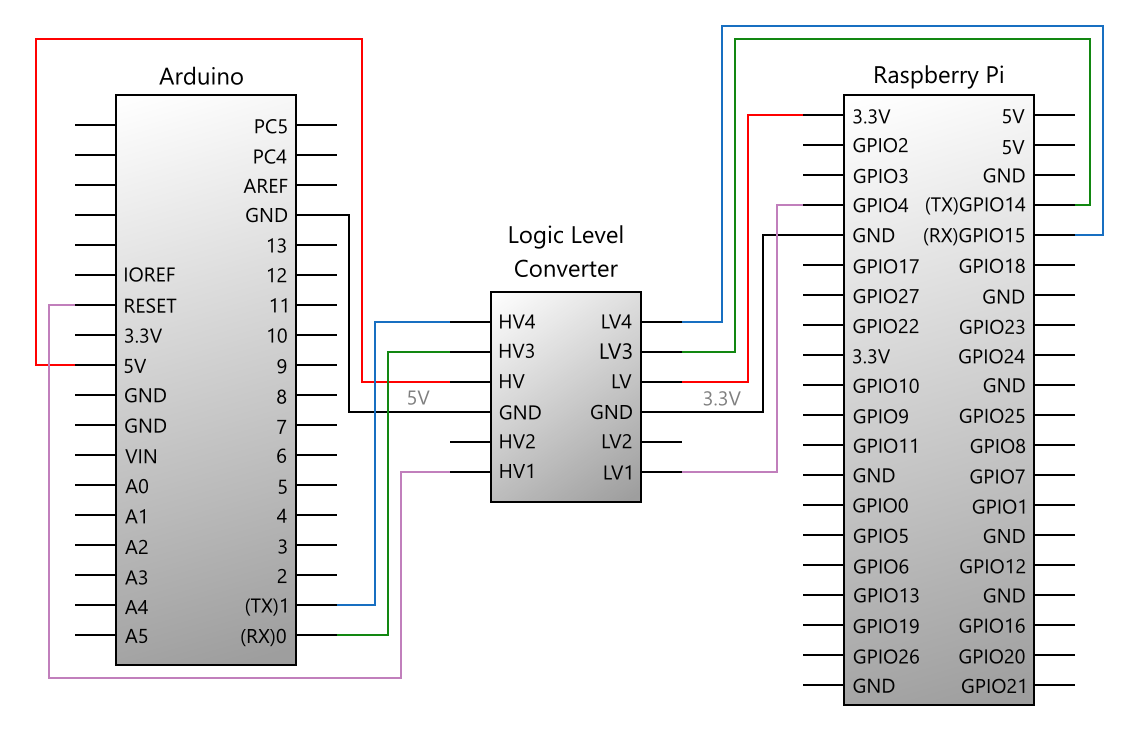
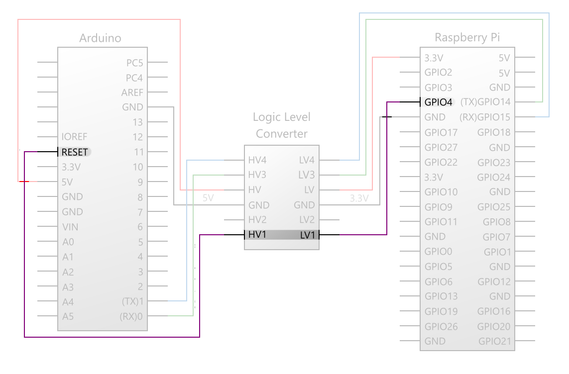
In the diagram above, notice the purple connection between the Arduino RESET and RPi GPIO 4 pins.cThis circuit is not part of the serial data connection but is instead used to reset the Arduino, and covered in the Electrically Resetting the Arduino from the RPi section later.
Ensure the Arduino is connected to the high voltage (HV) side and the RPi is connected to the low voltage (LV) side.
There's nothing special about any of the four channels of the logic level converter. Any channel can be used for any signal.
- HV4 to LV4 (any signal)
- HV3 to LV3 (any signal)
- HV2 to LV2 (any signal)
- HV1 to LV1 (any signal)
Testing Serial Connectivity
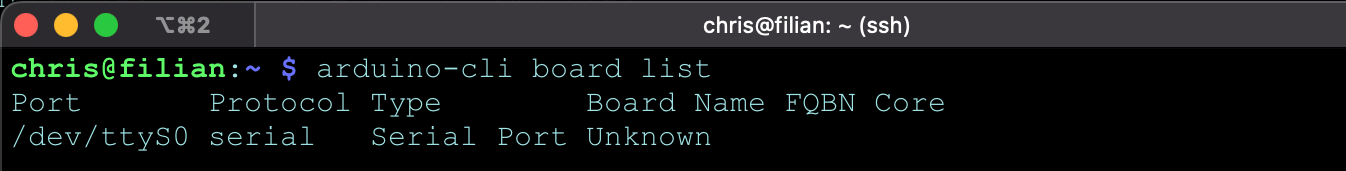
Once connected by USB or GPIO, run the board list command to determine if the RPi can detect your Arduino.
arduino-cli board list
An Arduino connected via USB should show under port /dev/ttyACM0.
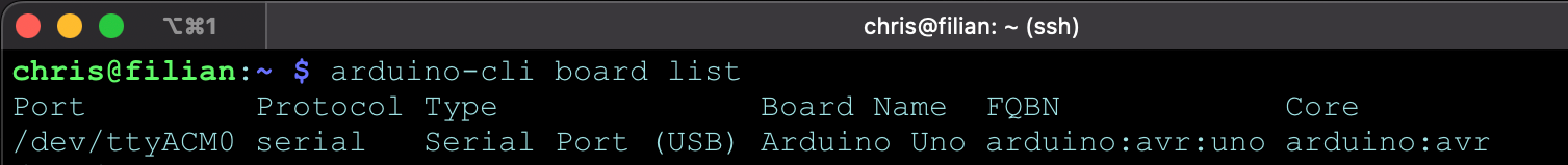
An Arduino connected via GPIO pins should show under port /dev/ttyS0.
Note that the Arduino is listed as Unknown in this example. The board showing as unknown doesn't necessarily mean there is a problem with the connection. Currently boards connected over GPIO may not be correctly indentified.
Electrically Resetting the Arduino from the RPi
The last step of flashing code to an Arduino requires a hard reset of the device. You will also want to be able to reset the Arduino from the RPi beyond just code changes. The Arduino may hang because of an error or memory issue. Consider a scenario where an Arduino activates a water pump and hangs, resulting in flooding a room.
You may be tempted to leverage the fact that the Arduino resets upon opening and closing a serial connection to handle fault resets. However, relying on a software-based reset is dubious at best! It assumes the Arduino is still responding. The only truly dependable method of resetting the Arduino is by pulling the 5V RESET pin low by connecting it to ground; this is actually what happens behind the scenes when you depress the physical reset button on the Arduino.
⚠️ Warning: As mentioned above in the discussion of the RPi GPIO pins, it's essential to understand that the Arduino and RPi operate at different logic voltages. Connecting the 5V Arduino RESET pin to any of the RPi 3.3V pins will damage the RPi!
If you are using the RPi GPIO pins and already using a logic level converter, hard resetting the Arduino is easily solved by using a spare channel on the converter between the Arduino RESET pin and any RPi GPIO pin and pulling it low. If, however, you are using USB you will need a safe way to pull the 5V RESET pin low from the 3.3V RPi. Perhaps the cheapest and easiest method is to use a transistor as a switch.
Reset Via Logic Level Converter (When Using GPIO)
Wiring the Arduino RESET pin to one of the RPi GPIO pins (GPIO 4 in this example) and programmatically pulling that GPIO pin low will initiate a hard reset of the Arduino.
Reset Via Transistor (When Using USB)
One method of resetting the Arduino while keeping the RPi safe from overvoltage is to use a transitor between them. Applying current from the RPi to the BASE pin of a transistor will open a gate between the COLLECTOR and EMITTER pins of the Arduino. The 5V current of the Arduino will not flow into the RPi through the transistor.
The following or similar components are needed:
- Transistor PN2222 ($0.55 Sparkfun link)
- 1k Resistor ($1.25 Sparkfun link)
Wiring a RPi GPIO pin (GPIO 24 in this example) to the Base pin of a transistor, through a resistor, and programmatically setting that pin high, will open the gate (or close the switch) of the transistor. Thus allowing current to flow between the Arduino RESET and Ground pins.